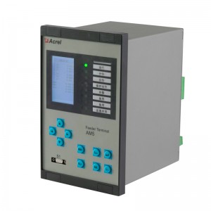
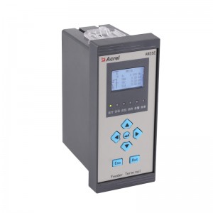
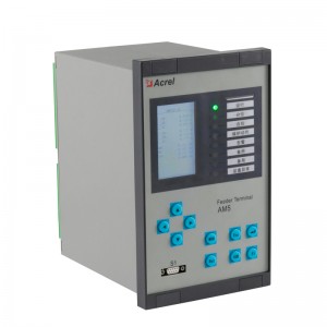
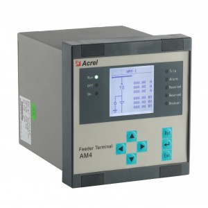
Acrel AM3SE Protection Relay
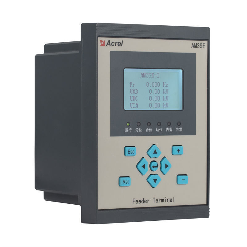
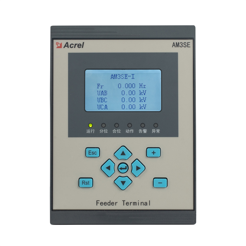
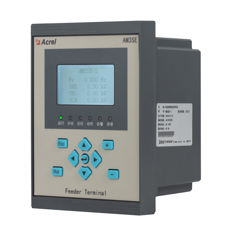
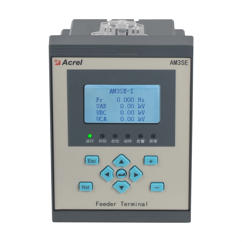
Acrel AM3SE Protection Relay
General
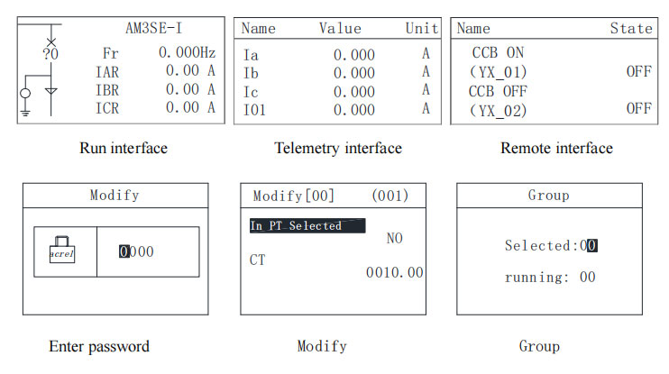
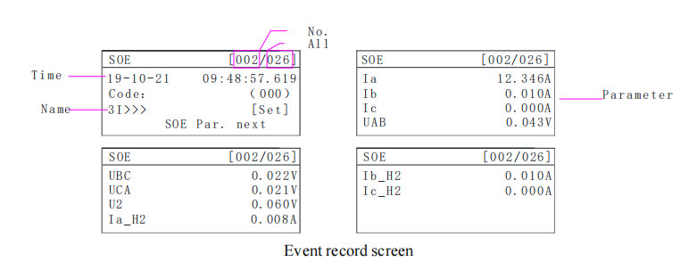
LCD Display
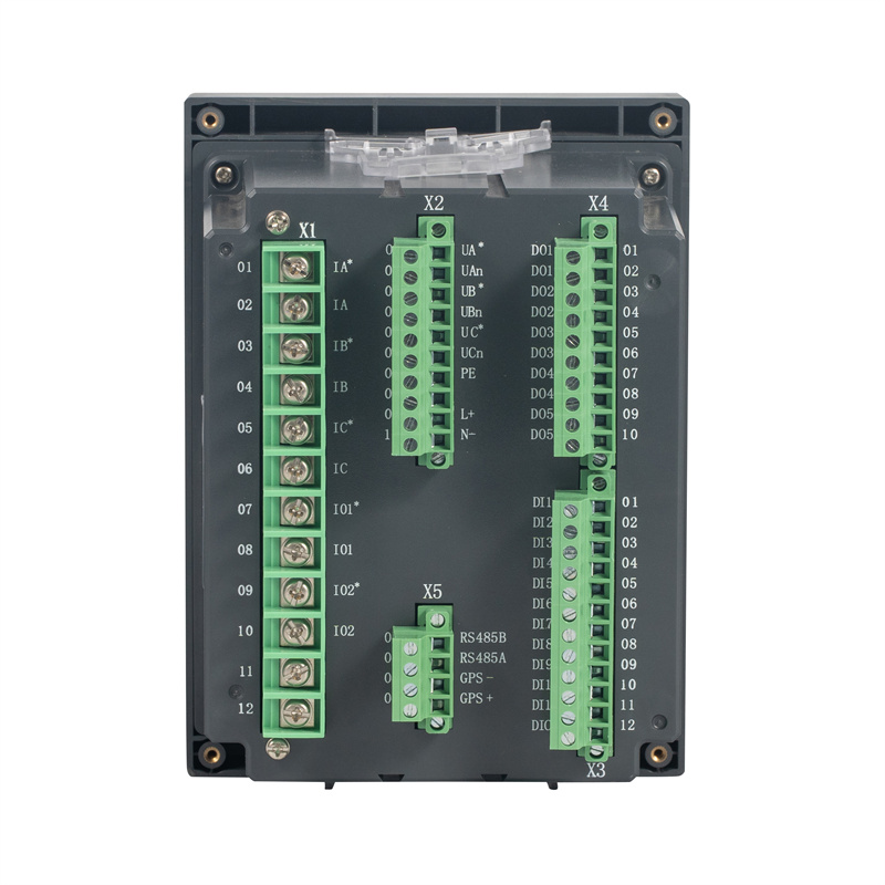
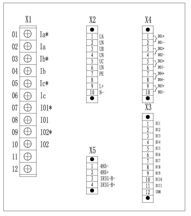
Wiring
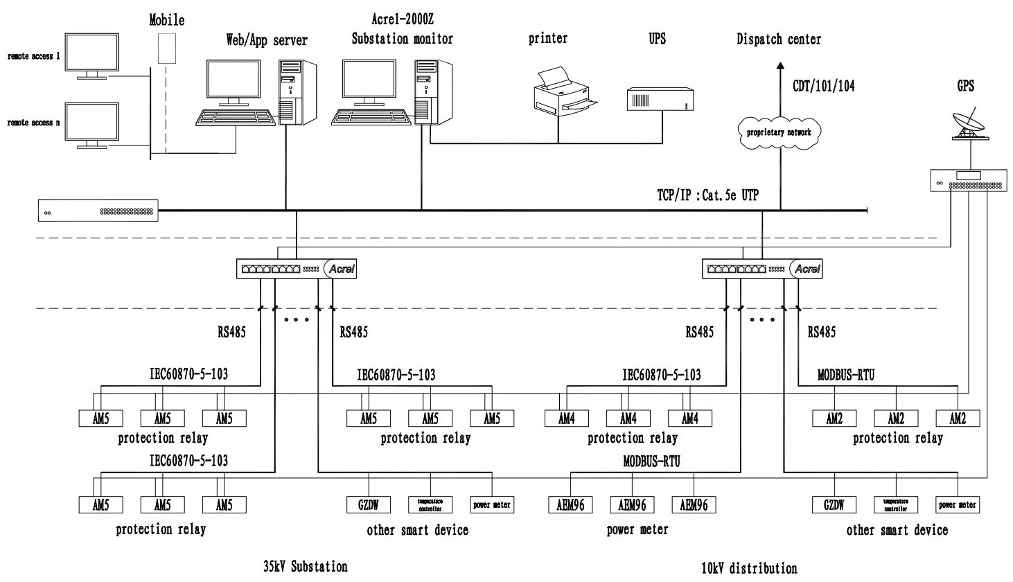
Network
AM3SE Protection Relay FAQs
The protection device can set the CT and PT ratio through the fixed value menu. For example, the current transformer is 75/5 and the voltage transformer is 10/0.1, then the CT ratio is set to 15 and the PT ratio is set to 100.
A AM3SE is suitable for circuit protection and transformer protection. No need to distinguish between models when placing orders.
The voltage wiring mode and current wiring mode of the protection device can be set independently, and can be connected freely.
If the circuit breaker is equipped with anti-trip, the device does not must be equipped with anti-trip; if the circuit
breaker does not have anti-trip, you need to configure the AM5-FT anti-trip module. (If DC48V is selected as the
operating power supply, the anti-trip box is not optional, and the circuit breaker must be equipped with anti-trip
function; if you choose AC anti-trip, please note that AC and DC general anti-tripping).
Before ordering, it is recommended to consult related engineers, select the appropriate protection model,
and then fill in the corresponding selection table, and place the order after confirmation by the engineers.
Acrel AM3SE Protection Relay
Technical Parameters
|
Characteristics / Version
|
AM3SE
|
|
Power Supply
|
|
|
Rated voltage
|
AC/DC 110V or AC/DC 220V or DC 48V or DC 24V
|
|
Range
|
Rated voltage × (1±20%)
|
|
Burden
|
≤10W ( DC )
|
|
PT Inputs
|
|
|
Rated value
|
AC 100V or 100 √3 V
|
|
PT rated secondary range
|
0.1V~120V
|
|
Accuracy
|
0.5S
|
|
Burden
|
≤0.5VA (each phase)
|
|
Voltage withstand
|
Continuous: 1.2 Un
10s: 2 Un
|
|
Phase CT Inputs (Protection Current)
|
|
|
CT rated secondary range
|
AC 5A or 1A
|
|
Dynamic
|
15 × CT rated current
|
|
Accuracy
|
0.5S
|
|
Burden
|
≤0.5VA (each phase)
|
|
Thermal withstand
|
Continuous: 2 In
1s: 40 In
|
|
Frequency
|
|
|
Rated frequency
|
50Hz or 60Hz
|
|
Frequency range
|
45 ~ 55Hz or 60Hz
|
|
Accuracy
|
±0.1Hz
|
|
Digital Inputs
|
|
|
Operating nominal voltage
|
AC/DC 110V or AC/DC 220V or DC48V or DC24V
|
|
Voltage threshold
|
70% of nominal voltage
|
|
Reset threshold
|
55% of nominal voltage
|
|
Burden
|
≤ 1W (each phase) (DC220V)
|
|
Digital Outputs
|
|
|
Make and carry
|
≥ 10000 operations
|
|
Making capacity
|
≥ 1000W, L / R = 40ms
|
|
Continuous current
|
≥ 5A
|
|
Short duration carry current
|
≥ 30A for 200ms
|
|
Breaking capacity
|
≥ 30W, L/R = 40ms
|
|
Characteristics
|
Accuracy
|
Resolution
|
Disengaging ratio
|
|
Voltage
|
±3%
|
0.001V
|
0.95 and 1.05
|
|
Current
|
±3%
|
0.001A
|
0.95 and 1.05
|
|
Frequency
|
±0.02Hz
|
0.001Hz
|
|
|
Inverse Time Element
Operation delay|t>(IDMT)
|
40ms or ±5% setting value
|
0.001s
|
- |
|
Time Element
Operation delay|t>(DT)
|
≤40ms [delay time within 2 seconds]
≤40ms ±1% setting value [delay time larger than 2 seconds]
|
0.001s
|
- |
|
Characteristics
|
Description/Value
|
|
Operating Temperature
|
-10℃~+55℃
|
|
Storage
|
-25℃~+70℃
|
|
Humidity
|
5%~95% (No condensation and freeze inside)
|
|
Altitude
|
≤2500m
|
|
Characteristics
|
Description/Value
|
|
Insulation Resistance
|
>100MΩ, 500Vdc
|
|
Dielectric Strength
|
Between circuits and ground, and between independent circuits:
Power frequency withstand voltage 2kV
|
|
Impulse Voltage
|
±5kV (1.2/50μs, 0.5J)
|
|
Characteristics
|
Standard
|
Level/Class
|
|
Radiated emission
|
IEC-60255-26:2023——5.1
|
A
|
|
Conducted emission
|
IEC-60255-26:2023——5.2
|
A
|
|
Radiated radio frequency fields
|
IEC-60255-26:2023
|
A
|
|
Electrostatic discharge
|
IEC-60255-26:2023——6.1
|
B
|
|
Conducted radio frequency disturbance
|
IEC-60255-26:2023——6.2-6.5
|
A
|
|
Fast transient bursts
|
IEC-60255-26:2023——6.2-6.5
|
B
|
|
Slow damped oscillatory waves
|
IEC-60255-26:2023——6.2-6.4
|
B
|
|
Surges
|
IEC-60255-26:2023——6.2-6.4
|
B
|
|
Voltage dips and short interruptions test
(AC or DC)
|
IEC-60255-26:2023——6.2
|
A/C 1
|
|
Magnetic field at power frequency
|
IEC-60255-26:2023——6.1
|
B
|
|
Protection functions
|
AM3SE
|
|
| I | U | |
|
Overcurrent (3 stages,IDMT)
|
■
|
|
|
Earth fault (3 stages,IDMT)(I01/I02)
|
■
|
|
|
Negative sequence overcurrent (2 stages,IDMT)
|
■
|
|
|
Auto-reclose
|
■
|
|
|
Overload (trip/alarm)
|
■
|
|
|
Under frequency
|
■
|
|
|
Post-accelerated overcurrent
|
■
|
|
|
Post-accelerated overcurrent(I01/I02)
|
■
|
|
|
Overvoltage(trip)
|
■
|
|
|
Undervoltage (trip)
|
■
|
|
|
Self-produced over zero-voltage (trip)
|
■
|
|
|
Residual overvoltage (trip)
|
■
|
|
|
FC block
|
■
|
|
|
Trip and close circuit supervision (alarm)
|
■
|
|
|
Non-electricity (trip/alarm)
|
■
|
|
|
Undervoltage (alarm)
|
■
|
■
|
|
Overvoltage (alarm)
|
■
|
■
|
|
Residual overvoltage (alarm)
|
■
|
■
|
|
Over frequency
|
■
|
|
|
Voltage phase loss protection
|
■
|
|
|
PT supervision (alarm)
|
■
|
■
|
|
Self-produced over zero-voltage (alarm)
|
■
|
|
|
Rear ports
|
I | U |
|
RS485
|
■
|
|
|
Protocols
|
I | U |
|
Modbus serial
|
■ | |
|
IEC 60870-5-103
|
■ | |
|
Measurement
|
I | U |
|
Electric parameter
|
U,I,P,Q,PF,Fr,Ep, Eq,Es
|
U,Fr
|
|
Input Current
|
5 | 0 |
|
Input Voltage
|
3 | 3 |
|
Logs and Records
|
I | U |
|
Fault recorder
|
■ | |
|
Sequence of event record
|
■ | |
|
Monitoring Functions
|
I | U |
|
Anti-pumping circuit
|
Optional
|
|
|
Remote control
|
■ | |