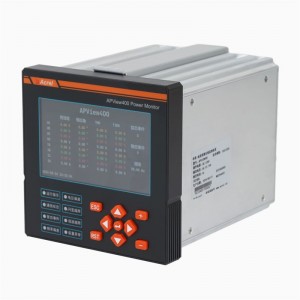
Acrel APView500 Power Quality Monitor
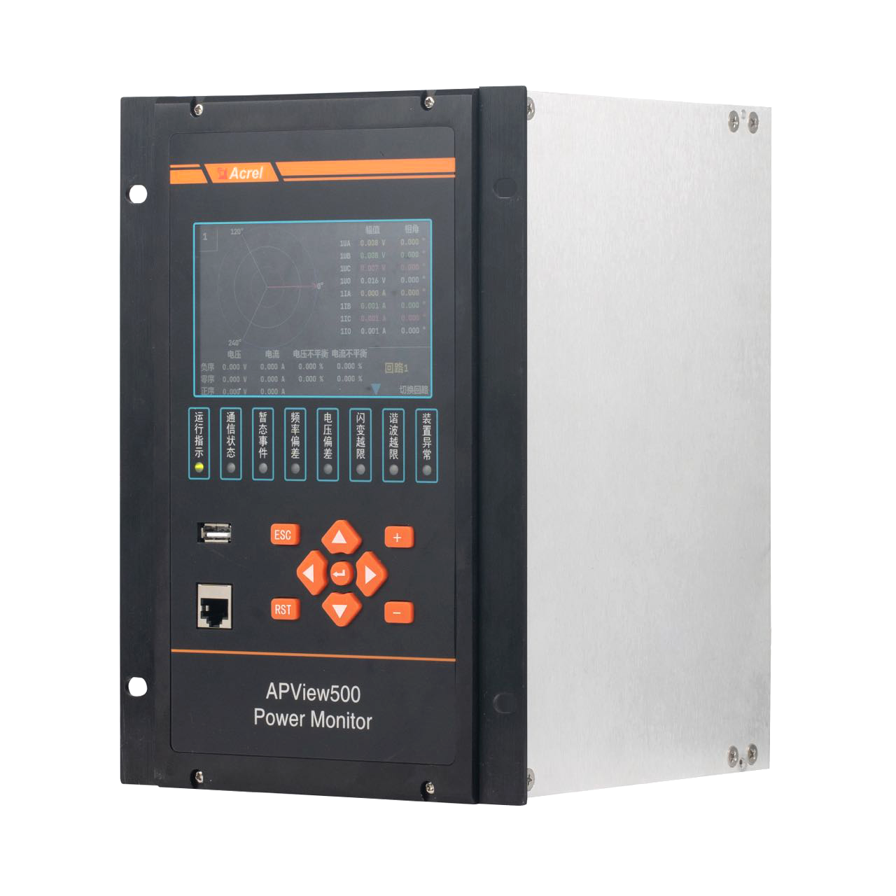


Acrel APView500 Power Quality Monitor
General
Acrel Power quality monitor APView500 integrates a high-performance multi-core platform and an embedded operating system, and monitors power quality indexes stipulated in IEC61000-4-30 Testing and measurement techniques –Power quality measurement methods, and provides various functions such as harmonic analysis, waveform sampling, voltage dips/swells/interruptions monitoring, flicker monitoring , voltage unbalance monitoring, event recording and measurement control. It meets IEC 61000-4-30 Class A Edition 3.1 with respect to standardization of power quality index measurement methods, measurement accuracy of index parameters, clock synchronization, event alarms and others and satisfy the demands of power quality monitoring of power supply system up to 110kV. Therefore, it is widely applicable for power quality monitoring in chemical industry, steel industry, metallurgy industry, hospitals, data centers, transportation, construction industry and other industries.
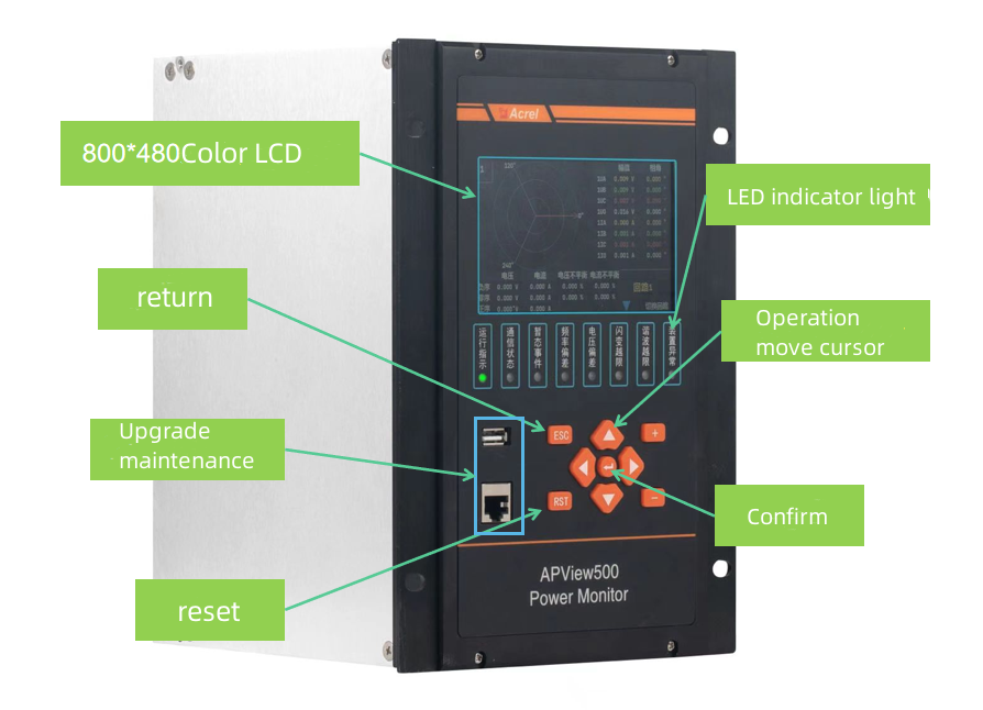
Front Panel
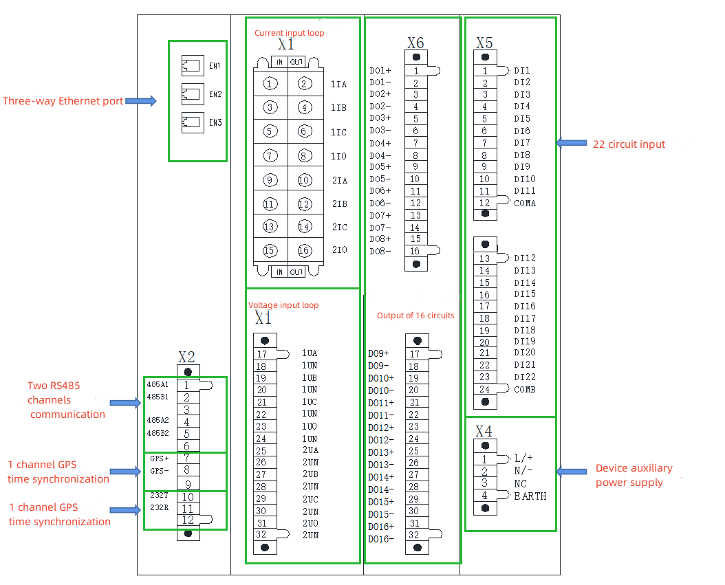
Wiring
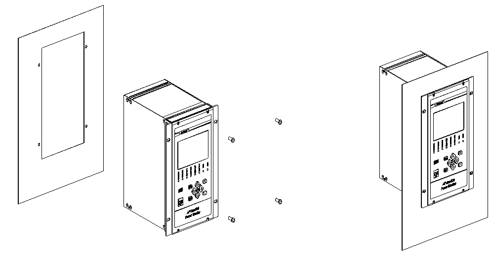
Installation
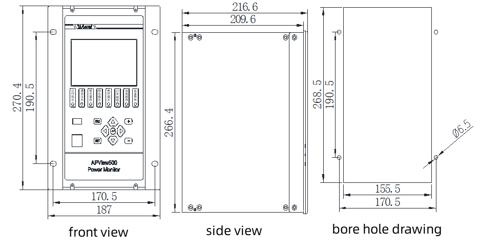
Outline and Dimension
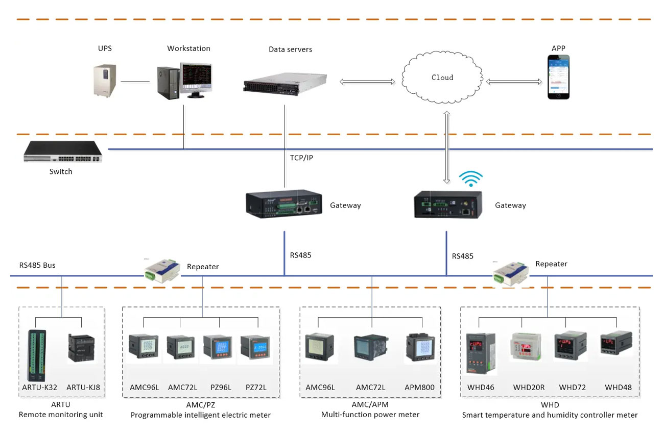
Typical Structure
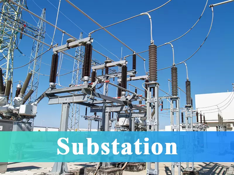
Application


Acrel APView500 Power Quality Monitor
Functions
|
Steady state |
RMS voltage and current |
√ |
||
| Frequency |
√ |
|||
| Fundamental phase angle and vector diagram |
√ |
|||
| Real-time voltage and current waveform display |
√ |
|||
| P、Q、S、PF |
√ |
|||
| Ep+、Ep-、Eq+、Eq- |
√ |
|||
| Voltage and Current sequence components |
√ |
|||
| Current and voltage unbalance |
√ |
|||
| Voltage deviation |
√ |
|||
| Frequency deviation |
√ |
|||
|
Harmonics (2nd -63rd)
|
Harmonic voltage/current RMS |
√ |
||
| Harmonic voltage/current ratio |
√ |
|||
| Total harmonic distortion(THD) of voltage/current |
√ |
|||
| Total demand distortion(TDD) of current |
√ |
|||
| Harmonic voltage/current phase angle |
√ |
|||
| Crest factor |
√ |
|||
| K-factor |
√ |
|||
| Odd harmonic distortion |
√ |
|||
| Even harmonic distortion |
√ |
|||
| Harmonic energy |
√ |
|||
| Harmonic power |
√ |
|||
|
Interharmonics (0.5th to 62.5th) |
Interharmonic voltage/current RMS |
√ |
||
| Interharmonic voltage/current ratio |
√ |
|||
|
Higher harmonics |
2.5kHz~8.9kHz |
√ |
||
| Voltage flicker (short-term flicker & long-term flicker) |
√ |
|||
| Voltage fluctuation |
√ |
|||
| Rapid voltage changes |
√ |
|||
|
Temporary state |
Voltage interruption |
√ |
||
| Voltage dip |
√ |
|||
| Voltage swell |
√ |
|||
| Inrush current |
√ |
|||
| Transient Current |
√ |
|||
|
Event recorder |
Temporary event | Trigger threshold of temporary event |
√ |
|
| Steady event | Trigger threshold of steady event |
√ |
||
| Log | Record the daily operation and running conditions |
√ |
||
|
Waveform recorder |
Event-triggered recording | Settable fault wave period |
√ |
|
| Manual recording | Settable recording sampling point |
√ |
||
| Timed recording | Settable recording sampling point |
√ |
||
| Host-triggered recording | Settable recording sampling point (supported by IEC61850 protocol) |
√ |
||
|
Communication |
IEC61850 |
■ |
||
| Modbus-RTU |
√ |
|||
| Modbus-TCP |
√ |
|||
| WebServer |
√ |
|||
|
Timing |
GPS timing(IRIG-B) |
√ |
||
| SNTP |
√ |
|||
| Manual timing |
√ |
|||
|
Hardware resources |
AI | 16 | Analog input |
■ |
| DO | 16 | Settable digital output |
√ |
|
| DI | 22 | Digital input(passive contacts requiring an external power supply) |
■ |
|
| USB | 1 | Maintenance |
√ |
|
| RS485 | 2 |
√ |
||
| RS232 | 1 | Maintenance |
√ |
|
| GPS port | 1 |
√ |
||
| Ethernet port | 4 | 1 port on the front panel for maintenance and another 3 ports on the rear panel for communication |
√ |
|
Input Configuration Table of APView500
|
Model and spec. |
Main configurations |
Scope of applications |
|
1U1I |
1x 3P voltage |
Single-bus single-incoming system |
|
2U2I |
2x 3P voltage |
Single-bus double-incoming (segmented/ unsegmented) system |
Monitor Accuracy
|
Basic functions |
Accuracy |
||
|
Steady state |
RMS Voltage |
±0.1% |
|
|
RMS Current |
±0.1% |
||
|
P,Q,S |
±0.2% |
||
|
Power factor |
±0.5% |
||
|
Ep+,Ep-,Eq+,Eq- |
Class 0.5 |
||
|
Voltage deviation |
0.1% |
||
|
Frequency deviation |
±0.001Hz |
||
|
Three-phase unbalance |
Voltage unbalance |
±0.15% |
|
|
Current unbalance |
±1% |
||
|
Harmonics (2nd -63rd) |
Harmonic voltage RMS |
When ≥1%,the error is ±5%. Error calculation: |
|
|
When<1%,the error is ±0.05%. Error calculation: |
|||
|
Harmonic current RMS
|
When ≥3%,the error is ±5%. error calculation: |
||
|
When <3%,the error is ±0.15%. Error calculation: |
|||
|
Interharmonics (0.5th to 62.5th) |
Interharmonic voltage RMS
|
When ≥1%,the error is ±5%. Error calculation: |
|
|
When<1%,the error is ±0.05%. Error calculation: |
|||
|
Harmonic Current RMS
|
When ≥3%,the error is ±5%. error calculation: |
||
|
When <3%,the error is ±0.15%. Error calculation: |
|||
|
Higher harmonics |
2.5kHz~8.9kHz |
||
|
Voltage flicker |
±5% |
||
|
Voltage fluctuation |
±0.2%Un |
||
|
Rapid voltage changes |
±0.2%Un |
||
|
Manual/Timed record |
Settable sampling points/ cycle |
||
|
Temporary state |
Event type |
Voltage dip |
Amplitude error: <±0.2%; time error: <±20ms |
|
Voltage swell |
Amplitude error: <±0.2%; time error: <±20ms |
||
|
Voltage interruption |
Amplitude error: <±0.2%; time error: <±20ms |
||
|
Inrush current |
Amplitude error: <±0.2%; Time error: <±20ms |
||
|
Temporary event record |
1024 points/ cycle |
||
|
Transient state |
Transient voltage |
20us |
|
|
Transient voltage |
20us |
||
|
Transient event record |
1024 points/ cycle |
||
|
Timing |
IRIG-B |
Absolute timing accuracy: ±1ms; clock accuracy: ±1s/24h |
|
|
SNTP |
Absolute timing accuracy: ±1ms; clock accuracy: ±1s/24h |
||