
Abstract: With the continuous growth of electricity demand, increasingly stringent requirements are being placed on the reliability of power system supply. Many power supply systems are now equipped with two or more incoming feeder circuits. Automatic Transfer Switching (ATS) devices can effectively improve power supply reliability. Such devices can automatically and rapidly switch the standby power source into service or transfer loads to the standby power source when the primary power source is disconnected due to a fault. The AM5SE-B high-voltage ATS device introduced in this paper was specially programmed for the unique configuration of this project, which consists of two utility incoming feeders, one bus-tie breaker, and two diesel generator feeders. The device was integrated into the existing secondary circuits on site. The ATS scheme implemented segmented bus transfer and diesel generator backup transfer functions, significantly improving the reliability, safety, and power quality of substation operation. It is also beneficial for realizing substation integrated automation and unattended or minimally attended operation.
Keywords: Reliability; Automatic Transfer Switching (ATS); ATS Device
1. Project Overview
This project involved the renovation of the 10 kV section of a military substation. The primary objective was to add ATS control functions to the existing protection secondary circuits, enabling automatic transfer to a standby power source when the primary power source experiences voltage loss or a fault, thereby ensuring continuous power supply to critical loads.
ATS devices play a crucial role in military projects, mainly in the following aspects:
①Power Supply Continuity and High Reliability: Military projects require extremely high power supply continuity. Any power outage may affect critical tasks such as command communications and combat readiness operations. The ATS device can rapidly and automatically switch to a standby power source (another incoming feeder or a diesel generator) when the primary power source fails, thereby improving power supply reliability.
②Enhanced Emergency Response Capability: In emergency situations, the primary power source may be damaged or disconnected. The ATS device can automatically switch to the standby power source according to preset logic without manual intervention, reducing power restoration time and ensuring continuous operation of critical loads.
③Reduced Management Costs: The ATS device reduces the workload associated with manual power source switching. Particularly in large facilities with multiple power sources, it can significantly reduce labor requirements and save human resource costs.
④Switching Between Different Power Supply Modes: The ATS device and ATS panel used in this project were manufactured by Acrel Electric and supplied with internal panel wiring. Zhonghuan Electric Co., Ltd. was responsible for completing the remaining on-site retrofit work and wiring from the original secondary circuits to the ATS panel.
The 10 kV power distribution system of this project mainly consists of two 35 kV/10 kV station service transformer incoming feeders, one bus-tie breaker, and two diesel generator incoming feeders. The simplified single-line diagram is shown in Figure 1.
QF1 and QF2 are the primary incoming feeders. Under normal operating conditions, the bus-tie breaker QF12 remains open, and the two station service transformer feeders operate independently. The diesel generator feeders QFY1 and QFY2 serve as backup power sources for the station service transformer feeders.
A single ATS panel was employed to collect voltage signals from the two station service transformer feeders and the two diesel generator feeders, breaker position signals from all breakers, and protection operation signals from the existing 10 kV incoming feeder and bus-tie protection relays. The panel also integrated opening and closing control outputs for five circuit breakers to realize ATS switching control of the 10 kV system.
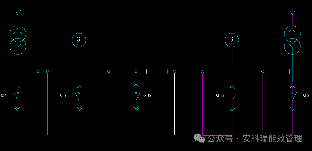
Figure 1. 10 kV Single-Line Diagram
2. ATS Scheme
The ATS device in this project acquires voltage and current signals from the two station service transformer feeders, voltage signals from the two diesel generator feeders, and position signals from five circuit breakers. The required ATS functions are as follows:
1) Normal Operating Condition
Under normal operation, incoming feeders QF1 and QF2 are closed, while the bus-tie breaker QF12 and diesel generator feeders QFY1 and QFY2 are open. The two incoming feeders operate independently.
When the ATS device detects that voltage, current, and breaker position statuses are normal, it enters the charged state after a preset delay.
2) Voltage Abnormality on Incoming Feeder 1 Only
① Station Service Transformer #1 Failure
When Station Service Transformer #1 becomes abnormal, the ATS device detects loss of voltage and current on Incoming Feeder 1. It then opens Incoming Feeder Breaker QF1 and closes Bus-Tie Breaker QF12, allowing Incoming Feeder 2 to supply the entire bus load.
② Recovery of Incoming Feeder 1 Voltage
When the ATS device detects restoration of voltage on Incoming Feeder 1, it enters the charging process in preparation for restoring power supply from Incoming Feeder 1.
After charging is completed, the ATS device opens Bus-Tie Breaker QF12 and closes Incoming Feeder Breaker QF1, restoring independent operation of the two incoming feeders.
3) Voltage Abnormality on Incoming Feeder 2 Only
① Station Service Transformer #2 Failure
When Station Service Transformer #2 becomes abnormal, the ATS device detects loss of voltage and current on Incoming Feeder 2. It then opens Incoming Feeder Breaker QF2 and closes Bus-Tie Breaker QF12, allowing Incoming Feeder 1 to supply the entire bus load.
② Recovery of Incoming Feeder 2 Voltage
When the ATS device detects restoration of voltage on Incoming Feeder 2, it enters the charging process in preparation for restoring power supply from Incoming Feeder 2.
After charging is completed, the ATS device opens Bus-Tie Breaker QF12 and closes Incoming Feeder Breaker QF2, restoring independent operation of the two incoming feeders.
4) Voltage Abnormalities on Both Incoming Feeders 1 and 2
① Complete Utility Power Failure
When the ATS device detects loss of voltage and current on both Incoming Feeders 1 and 2, the two diesel generators are automatically started on site. The ATS device trips Incoming Feeder Breakers QF1 and QF2.
② Diesel Generator Backup Operation
After confirming that both station service transformer feeder breakers and the bus-tie breaker have opened, the ATS device monitors the voltages of the two diesel generator feeders.
a. Both Diesel Generator Feeders Energized
When both diesel generator feeders are energized, the ATS device determines that both diesel generators have started successfully. The ATS device then closes Diesel Generator Feeder Breakers QFY1 and QFY2, allowing Diesel Generator 1 and Diesel Generator 2 to supply Loads on Bus Section I and Bus Section II respectively.
If Utility Incoming Feeder 1 recovers first, both diesel generator feeders are disconnected. The ATS device then closes Incoming Feeder Breaker 1 followed by the bus-tie breaker, allowing Incoming Feeder 1 to supply the entire bus load.
If Utility Incoming Feeder 2 recovers first, both diesel generator feeders are disconnected. The ATS device then closes Incoming Feeder Breaker 2 followed by the bus-tie breaker, allowing Incoming Feeder 2 to supply the entire bus load.
If Utility Incoming Feeders 1 and 2 recover simultaneously, both diesel generator feeders are disconnected. The ATS device then closes Incoming Feeder Breakers 1 and 2, restoring independent operation of the two incoming feeders.
b. Diesel Generator Feeder QFY1 Energized and QFY2 De-Energized
When the ATS device detects voltage on Diesel Generator Feeder QFY1 but no voltage on Diesel Generator Feeder QFY2, it determines that Diesel Generator 1 has started successfully while Diesel Generator 2 has failed.
The ATS device then closes Diesel Generator Feeder Breaker QFY1 and Bus-Tie Breaker QF12, allowing Diesel Generator 1 to supply the entire bus load.
If Utility Incoming Feeder 1 recovers first, Diesel Generator Feeder QFY1 is disconnected, and Incoming Feeder Breaker 1 is closed to supply the entire bus load.
If Utility Incoming Feeder 2 recovers first, Diesel Generator Feeder QFY1 is disconnected, and Incoming Feeder Breaker 2 is closed to supply the entire bus load.
If Utility Incoming Feeders 1 and 2 recover simultaneously, Diesel Generator Feeder QFY1 and the bus-tie breaker are disconnected, and Incoming Feeder Breakers 1 and 2 are closed, restoring independent operation of the two incoming feeders.
c. Diesel Generator Feeder QFY2 Energized and QFY1 De-Energized
When the ATS device detects voltage on Diesel Generator Feeder QFY2 but no voltage on Diesel Generator Feeder QFY1, it determines that Diesel Generator 2 has started successfully while Diesel Generator 1 has failed.
The ATS device then closes Diesel Generator Feeder Breaker QFY2 and Bus-Tie Breaker QF12, allowing Diesel Generator 2 to supply the entire bus load.
If Utility Incoming Feeder 1 recovers first, Diesel Generator Feeder QFY2 is disconnected, and Incoming Feeder Breaker 1 is closed to supply the entire bus load.
If Utility Incoming Feeder 2 recovers first, Diesel Generator Feeder QFY2 is disconnected, and Incoming Feeder Breaker 2 is closed to supply the entire bus load.
If Utility Incoming Feeders 1 and 2 recover simultaneously, Diesel Generator Feeder QFY2 and the bus-tie breaker are disconnected, and Incoming Feeder Breakers 1 and 2 are closed, restoring independent operation of the two incoming feeders.
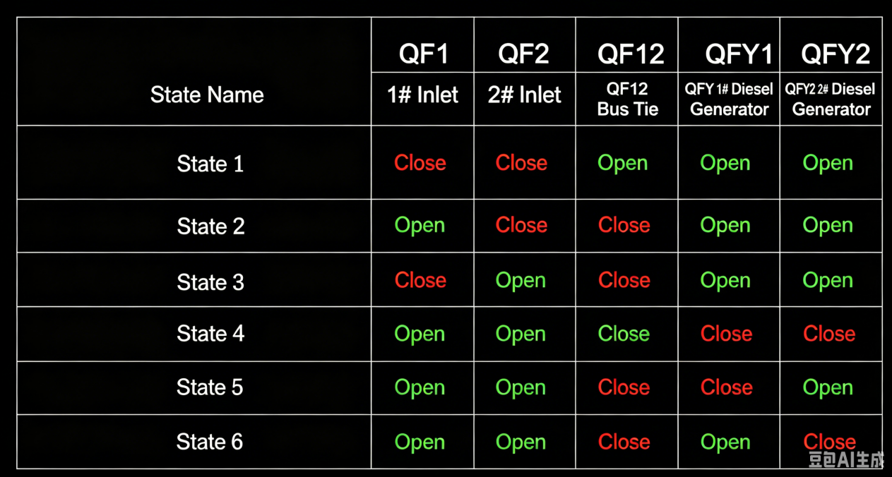
Figure 2. ATS Status Table
3. Product Solution
This project involved the installation of a new ATS panel equipped with an ATS device in the 10 kV switchroom and its integration into the existing control circuits.
The 10 kV system consists of two station service transformer incoming feeders, one bus-tie breaker, and two diesel generator feeders. One AM5SE-B high-voltage ATS device was installed, wired, and assembled into the panel at the factory before shipment.
After arriving on site, voltage signals, current signals, breaker position inputs, and control power were connected to the panel terminals. The ATS device was then used to provide opening and closing control for five circuit breakers.
At the same time, secondary wiring diagrams and terminal block drawings were prepared according to the site secondary schematic diagrams, providing documentation for panel assembly and on-site integration.
The terminal configuration at the rear of the device is shown in Figure 2.1.
Terminals X1.17–X1.20 are connected to Incoming Feeder 1 voltage inputs;
Terminals X1.21–X1.24 are connected to Incoming Feeder 2 voltage inputs;
Terminals X1.25–X1.26 are connected to Diesel Generator 1 voltage inputs;
Terminals X1.27–X1.28 are connected to Diesel Generator 2 voltage inputs.
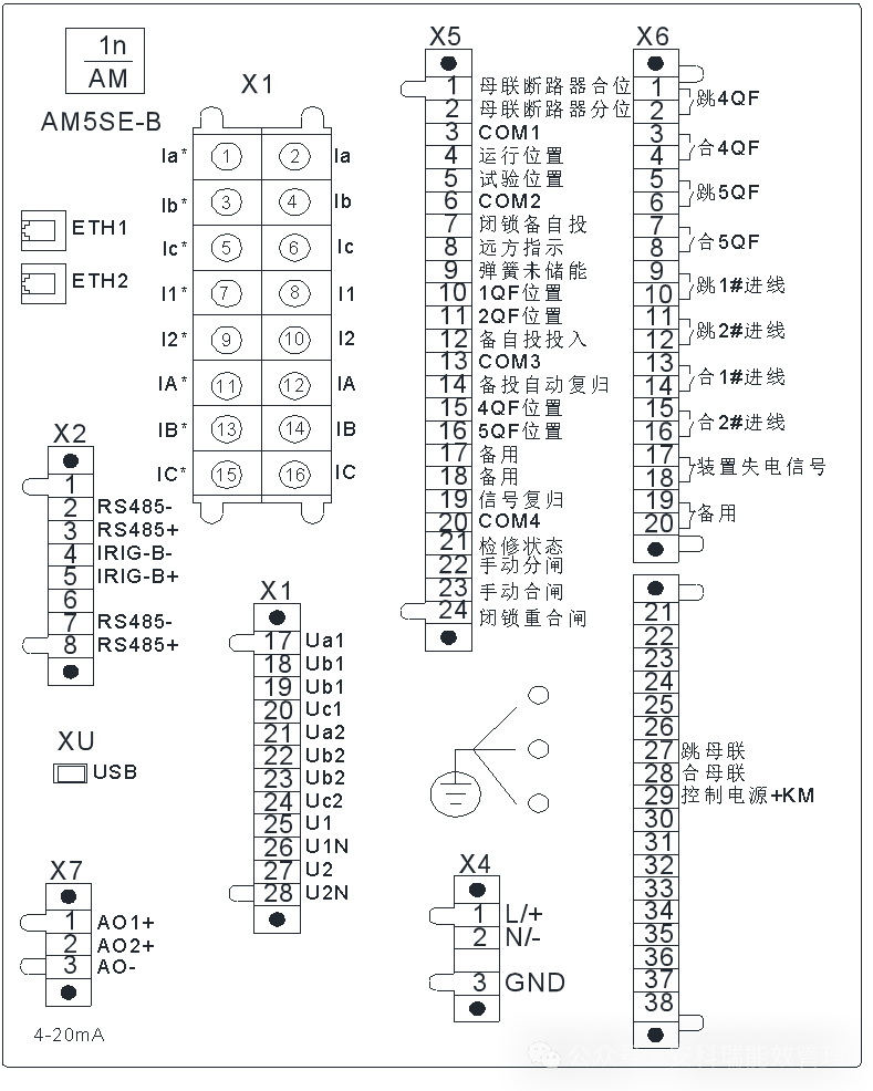
Figure 3.1 Rear terminal diagram of AM5SE-B ATS
4. Panel Solution and On-Site Commissioning
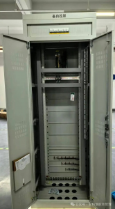
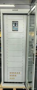
In this project, the AM5SE-B high-voltage ATS protection device was installed in the ATS panel.
Partial terminal wiring and reserved external terminal connections were completed during factory panel assembly. After delivery to the site, current, voltage, breaker position, and other digital input signals were connected according to the design drawings. Corresponding output circuits were connected to the opening and closing circuits of the controlled breakers.
Following on-site testing and commissioning, the system was successfully put into operation.
5. Conclusion
China's power supply mainly relies on the State Grid system. As electricity demand continues to increase, power shortages have become more significant, especially during peak load periods. As a result, many large enterprises have established their own power plants or installed generator sets.
Automatic Transfer Switching devices ensure uninterrupted power supply and improve power supply reliability. They have become an important component of protection and control systems in modern power distribution engineering.
The project described in this paper utilized the AM5SE-B high-voltage ATS protection device to realize switching among different power supply modes. This not only improved power supply reliability and enabled integrated automation of the entire power distribution system, but also effectively reduced the labor intensity of operating personnel and saved human resource costs.
Post time: Jul-23-2026