Acrel AM5SE Medium Voltage Line Protection Relay

Acrel AM5SE Medium Voltage Line Protection Relay
General
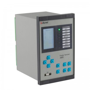
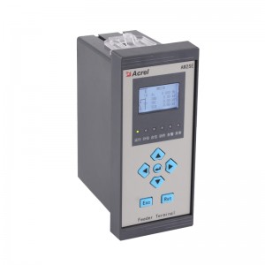
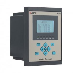
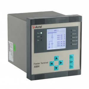
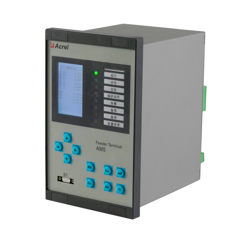
The AM5SE relay has the modular design and it can be optimized to almost all type of feeder protection applications in medium voltage distribution systems.
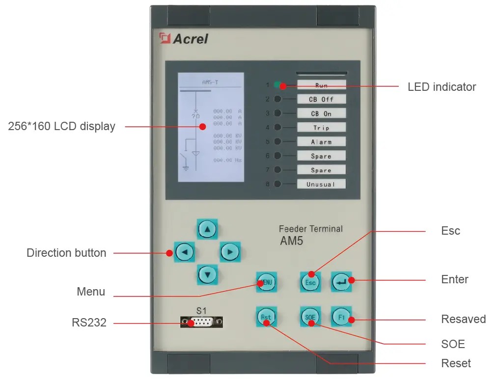
Front Panel
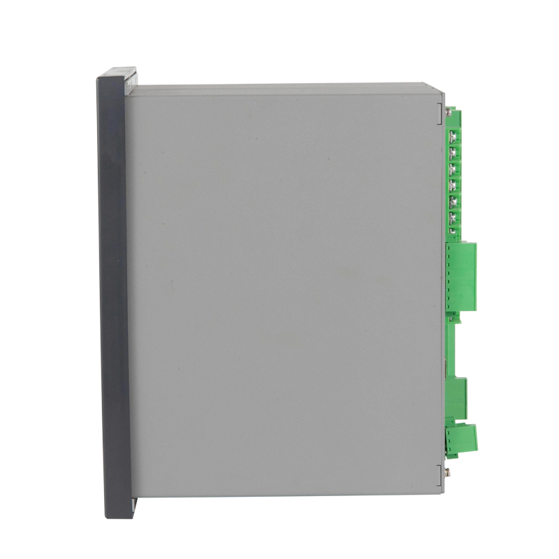
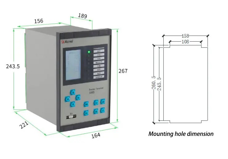
Dimension
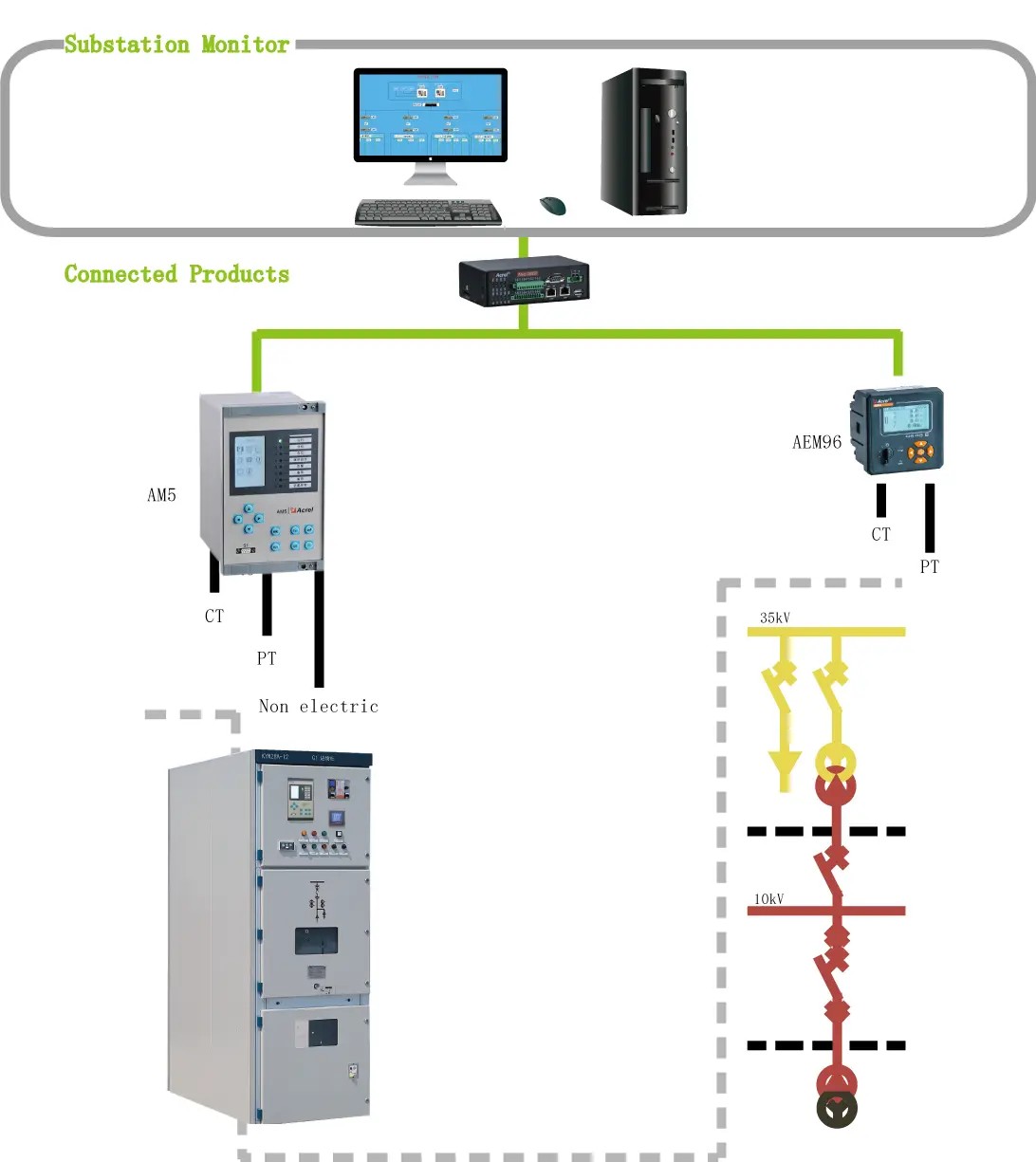
Network
Acrel AM5SE Medium Voltage Line Protection Relay
Technical Parameters
Rated Characteristics
|
Characteristics / Version
|
AM5SE-F,AM5SE-T,AM5SE-M,AM5SE-C,
AM5SE-B,AM5SE-D2,AM5SE-D3,
AM5SE-TB,AM5SE-MD
|
AM5SE-UB, AM5SE-IS, AM5SE-FE,
AM5SE-FA,AM5SE-K
|
|
Power Supply
|
||
|
Rated voltage
|
AC/DC 110V or AC/DC 220V
|
|
|
Range
|
Rated voltage × (1±20%)
|
|
|
Burden
|
≤15 VA
|
|
|
PT Inputs
|
||
|
Rated value
|
AC 100V or 100 √3 V
|
AC 380V or 220V
|
|
PT rated secondary range
|
0.1V~120V
|
0.1V ~ 456V
|
|
Accuracy
|
0.5S
|
|
|
Burden
|
≤0.5VA (each phase)
|
|
|
Voltage withstand
|
Continuous: 1.2 Un
10s: 2 Un
|
|
|
Phase CT Inputs (Protection Current)
|
||
|
CT rated secondary range
|
AC 5A or 1A
|
|
|
Dynamic
|
20 × CT rated current
|
|
|
Accuracy
|
0.5S
|
|
|
Burden
|
≤0.5VA (each phase)
|
|
|
Thermal withstand
|
Continuous: 2 In
1s: 40 In
|
|
|
Phase CT Inputs (Measurement Current)
|
||
|
CT rated secondary range
|
AC 5A or 1A
|
|
|
Dynamic
|
1.5 × CT rated current
|
|
|
Accuracy
|
0.5S
|
|
|
Burden
|
≤0.5VA (each phase)
|
|
|
Thermal withstand
|
Continuous: 1.5 In
1s: 4 In
|
|
|
Frequency
|
||
|
Operating nominal voltage
|
AC/DC 110V or AC/DC 220V
|
|
|
Voltage threshold
|
70% of nominal voltage
|
|
|
Reset threshold
|
55% of nominal voltage
|
|
|
Burden
|
≤ 1W (each phase) (DC220V)
|
|
|
Digital Outputs
|
||
|
Make and carry
|
≥ 10000 operations
|
|
|
Making capacity
|
≥ 1000W, L / R = 40ms
|
|
|
Continuous current
|
≥ 5A
|
|
|
Short duration carry current
|
≥ 30A for 200ms
|
|
|
Breaking capacity
|
≥ 30W, L/R = 40ms
|
|
Protection characteristics
|
Characteristics
|
Accuracy
|
Resolution
|
Disengaging ratio
|
|
Voltage
|
±3%
|
0.001V
|
0.95 and 1.05
|
|
Current
|
±3%
|
0.001A
|
0.95 and 1.05
|
|
Frequency
|
±0.02Hz
|
0.001Hz
|
|
|
Operation delay|t>(DT)
|
40ms or ±2% setting value
|
0.001s
|
- |
|
Operation delay|t>(IDMT)
|
40ms or ±5% setting value
|
0.001s
|
- |
Environmental characteristics
|
During operation
|
10℃~+55℃, temperature; 5%~95%, humidity
|
|
Storage
|
-25℃~+70℃
|
|
Altitude
|
≤ 2000m
|
|
Enclosure
|
IP20 (local panel)
|
Product safety
|
Insulation
|
Insulation resistance >100MΩat 500Vdc
|
|
High voltages withstand
|
2kV rms AC, 1 min:between all case terminals connected together, and the case earth/ground;
2 kV rms AC, 1 min:between all terminals of independent circuits
|
|
Impulse voltage
|
±5kV (1.2/50μs, 0.5J)
|
Electromagnetic Compatibility Characteristics
|
Characteristics
|
Standard
|
Level/Class
|
|
Radiated emission
|
IEC-60255-26:2023——5.1
|
A
|
|
Conducted emission
|
IEC-60255-26:2023——5.2
|
A
|
|
Radiated radio frequency fields
|
IEC-60255-26:2023
|
A
|
|
Electrostatic discharge
|
IEC-60255-26:2023——6.1
|
B
|
|
Conducted radio frequency disturbance
|
IEC-60255-26:2023——6.2-6.5
|
A
|
|
Fast transient bursts
|
IEC-60255-26:2023——6.2-6.5
|
B
|
|
Slow damped oscillatory waves
|
IEC-60255-26:2023——6.2-6.4
|
B
|
|
Surges
|
IEC-60255-26:2023——6.2-6.4
|
B
|
|
Voltage dips and short interruptions test
(AC or DC)
|
IEC-60255-26:2023——6.2
|
A/C 1
|
|
Magnetic field at power frequency
|
IEC-60255-26:2023——6.1
|
B
|
1
AC and DC voltage dips meet the criteria A/C of the IEC60255-26:2023—6.2. AC and DC voltage
interruptions meet the criteria C of the IEC60255-26:2023—6.2.Ripple on DC input power port immunity meet the
criteria A of the IEC60255-26:2023—6.2. DC auxiliary power supply ports gradually shortdown/start-up meet the
criteria C of the IEC60255-26:2023—6.2.
|
Analog inputs
|
AM5SE
|
||||||||||||||
| -F | -T | -M | -C |
-MD
|
-D2
|
-D3
|
-TB
|
-IS |
-FE
|
-FA
|
-B
|
-K
|
-UB
|
-FD
|
|
|
Input current
|
8 | 8 | 8 | 8 |
9
|
9
|
9
|
8
|
6 |
8
|
8
|
8
|
8
|
0
|
/ |
|
Input voltage
|
6 | 4 | 4 | 4 |
4
|
4
|
4
|
4
|
8 |
6
|
6
|
6
|
6
|
8
|
/ |
|
Digital
|
-F | -T | -M | -C |
-MD
|
-D2
|
-D3
|
-TB
|
-IS |
-FE
|
-FA
|
-B
|
-K
|
-UB
|
-FD |
|
Digital Input
|
20
|
20
|
20
|
20
|
20
|
20
|
20
|
20
|
20
|
20
|
20
|
20
|
20
|
20
|
12 |
|
Digital Output
|
10 | 10 | 10 | 10 |
10
|
10
|
10
|
10
|
10 |
10
|
10
|
10
|
10
|
10
|
64 |
|
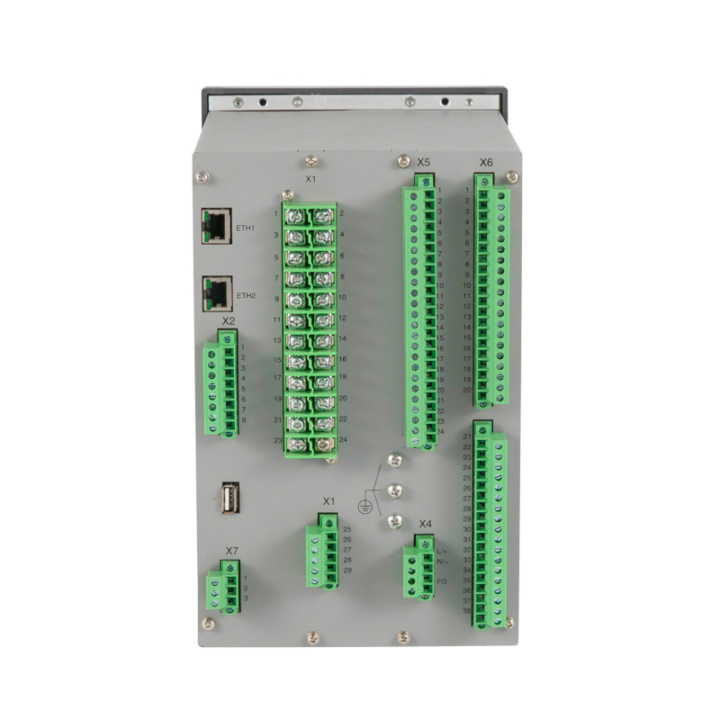
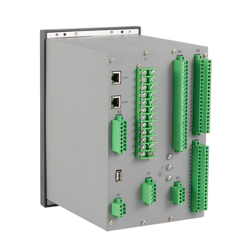
Rear port
|
-F | -T | -M | -C |
-MD
|
-D2
|
-D3
|
-TB
|
-IS |
-FE
|
-FA
|
-B
|
-K
|
-UB
|
-FD |
|
RS485 (2 ports)
|
√
|
||||||||||||||
|
Ethernet(2 ports)
|
■
|
||||||||||||||
|
USB(1 port)
|
√
|
||||||||||||||
|
Protocols
|
-F | -T | -M | -C |
-MD
|
-D2
|
-D3
|
-TB
|
-IS |
-FE
|
-FA
|
-B
|
-K
|
-UB
|
-FD |
|
Modbus Serial
|
√
|
||||||||||||||
|
Modbus over Ethernet
|
■ | ||||||||||||||
|
IEC 60870-5-103
|
√
|
||||||||||||||
|
TCP IEC 60870-5-103
|
■ | ||||||||||||||
|
IEC 60870-5-101
|
√
|
||||||||||||||
|
Measurement
|
-F | -T | -M | -C | -MD | -D2 | -D3 | -TB | -IS | -FE | -FA | -B | -K | -UB | -FD |
|
4-20mA analog output
|
■ | ||||||||||||||
|
Electric parameter
|
U、I、P、Q、PF、Fr、Ep、Eq、Es
|
U、I
|
U、Fr
|
||||||||||||
|
Logs and Records
|
-F | -T | -M | -C | -MD | -D2 | -D3 | -TB | -IS | -FE | -FA | -B | -K | -UB | -FD |
|
Fault recorder
|
√ | ||||||||||||||
|
Number of circuit breaker trip and close
|
√ | ||||||||||||||
|
Sequence of event record
|
√ | ||||||||||||||
|
Monitoring function
|
-F | -T | -M | -C | -MD | -D2 | -D3 | -TB | -IS | -FE | -FA | -B | -K | -UB | -FD |
|
Trip-and-Close Circuit Supervision
|
√
|
||||||||||||||
|
Remote control
|
√
|
||||||||||||||
|
Others
|
-F | -T | -M | -C | -MD | -D2 | -D3 | -TB | -IS | -FE | -FA | -B | -K | -UB | -FD |
|
GPS
|
√
|
||||||||||||||
|
Protection Function
|
-F | -T | -M | -C | -MD | -D2 | -D3 | -TB | -IS | -FE | -FA | -B | -K | -UB | -FD |
|
3 stages directional overcurrent
(with voltage dependant)[ANSI 67]
|
√
|
√
|
√
|
√
|
|||||||||||
|
3 stages overcurrent
(with composite voltage blocking)[ANSI 50/51]
|
√
|
√
|
√
|
√
|
√
|
||||||||||
|
Differential protection with ratio restraining[ANSI 87]
|
√
|
√
|
√
|
||||||||||||
|
Instantaneous Differential protection[ANSI 87]
|
√
|
√
|
√
|
||||||||||||
|
Motor overcurrent(motor start,motor run,2 stages)
|
√
|
√
|
|||||||||||||
|
Overcurrent (2 stages) [ANSI 50/51]
|
√
|
||||||||||||||
|
Overcurrent IDMT [ANSI 51N]
|
√
|
√
|
√
|
√
|
√
|
√
|
√
|
√
|
|||||||
|
Bus charge
|
√
|
||||||||||||||
|
Bus tie protection and standby power automatic switch
|
√
|
||||||||||||||
|
2 stages Directional earth fault
[ANSI 67N]
|
√
|
√
|
√
|
√
|
|||||||||||
|
2 stages earth fault [ANSI 50N/51N]
|
√
|
√
|
√
|
√
|
√
|
||||||||||
|
Earth fault IDMT[ANSI 50N/51N]
|
√
|
√
|
√
|
√
|
|||||||||||
|
Clearance earth fault protection(2 stages)
|
√
|
||||||||||||||
|
Negative sequence overcurrent (2 stages)[ANSI 46]
|
√
|
√
|
|||||||||||||
|
Negative sequence overcurrent IDMT[ANSI 46]
|
√
|
√
|
|||||||||||||
|
Overload [ANSI 49F]
|
√
|
√
|
√
|
√
|
√
|
||||||||||
|
Starting air-cooled water chiller
|
√
|
||||||||||||||
|
On-load tap charge lock-out
|
√
|
||||||||||||||
|
Undervoltage (trip)[ANSI 27]
|
√
|
√
|
√
|
√
|
√
|
||||||||||
|
Undervoltage (alarm)[ANSI 27]
|
√
|
√
|
√
|
√
|
√
|
√
|
|||||||||
|
Capacitor undervoltage(trip)
|
√ | ||||||||||||||
|
Loss of voltage (trip)
|
√ | √ | |||||||||||||
|
Loss of voltage (alarm)
|
√ | √ | |||||||||||||
|
Overvoltage protection[ANSI 59]
|
√ | √ | √ | √ | √ | √ | √ | ||||||||
|
Residual voltage protection(trip)[ANSI 59N]
|
√ | √ | √ | √ | √ | √ | |||||||||
|
Residual voltage protection(alarm)[ANSI 59N]
|
√ | √ | √ | ||||||||||||
|
PT supervision[ANSI 60]
|
√ | √ | √ | √ | √ | √ | √ | √ | √ | √ | √ | ||||
|
Unbalance voltage[ANSI 60]
|
√ | √ | √ | ||||||||||||
|
Unbalance current[ANSI 60]
|
√ | √ | |||||||||||||
|
Motor starting time-out[ANSI 48]
|
√ | √ | |||||||||||||
|
CT supervision[ANSI 60]
|
√ | √ | √ | √ | √ | √ | |||||||||
|
Three phase Auto-reclose[ANSI 79]
|
√ | ||||||||||||||
|
Thermal overload protection[ANSI 49M]
|
√ | √ | |||||||||||||
|
Locked rotor[ANSI 51LR]
|
√ | √ | |||||||||||||
|
FC block[ANSI 86]
|
√ | √ | √ | √ | √ | √ | |||||||||
|
Post-accelerated overcurrent
|
√ | √ | |||||||||||||
|
Under frequency[ANSI 81U]
|
√ | √ | √ | √ | |||||||||||
|
Over frequency[ANSI 81O]
|
√ | √ | √ | √ | |||||||||||
|
Incorrect phase sequence
|
√ | √ | |||||||||||||
|
Voltage Phase loss protection
|
√ | √ | |||||||||||||
|
Directional power protection[ANSI 32]
|
√ | √ | |||||||||||||
|
Power recovery protection
|
√ | ||||||||||||||
|
Under power protection
|
√ | ||||||||||||||
|
Non-electricity
|
√ | √ | √ | √ | √ | √ | √ | √ | |||||||
|
PT supervision and parallel connection
|
√ | ||||||||||||||
|
Synchro-check[ANSI 25]
|
√ | √ | √ | ||||||||||||
|
Rate of change of frequency[ANSI 81R]
|
√ | √ | |||||||||||||
|
Trip-and-Close Circuit Supervision(alarm)
|
√ | √ | √ | √ | √ | √ | √ | √ | √ | √ | |||||
|
Auto-close with voltage recovery
|
√ | ||||||||||||||
|
PT harmonic elimination
|
√ | ||||||||||||||
|
Overhaul-lockout[ANSI 86]
|
√ | ||||||||||||||
Note: √ means with this function, ■ means optional function, blank means without this function.